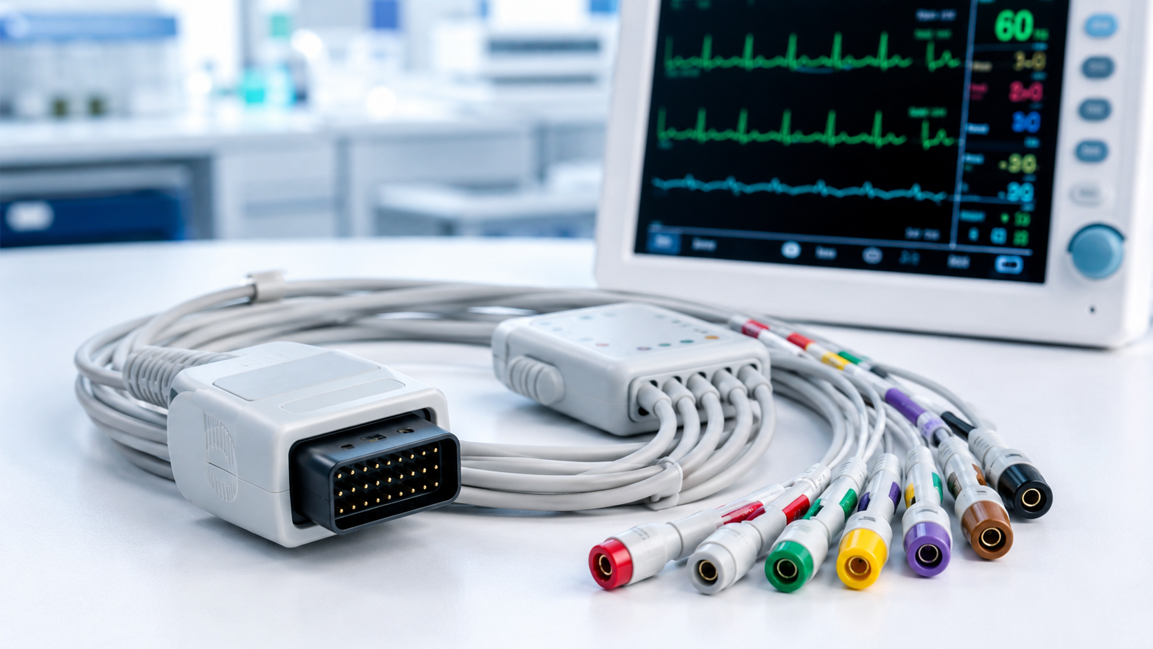
ECG leadwires and ECG trunk cables are both important components of a patient monitoring cable system, but they serve different functions within the overall ECG signal path.
The ECG trunk cable typically provides the connection between the patient monitor or ECG module and the patient-side leadwire assembly, while ECG leadwires connect the patient electrodes to the cable assembly.
Understanding the difference between ECG leadwires and trunk cables can help medical device OEMs define the correct cable architecture, connector interfaces, lead configuration and customization requirements before production.
ECG Leadwires vs ECG Trunk Cables: What’s the Difference?
Although ECG leadwires and ECG trunk cables are often discussed together, they are not interchangeable components. Their interfaces, functions and design requirements can be different depending on the architecture of the patient monitoring system.
| Feature | ECG Trunk Cable | ECG Leadwires |
| Main function | Connects the patient-side cable assembly to the monitor or ECG module | Connects electrodes to the trunk cable or compatible monitoring interface |
| Primary interface | Monitor-side connector and patient-side connector/yoke | Electrode termination and trunk-side connection |
| Typical components | Monitor connector, cable body, yoke or patient-side connector, strain relief | Individual lead wires, electrode connectors, insulation and strain relief |
| Common configurations | Device-specific cable and connector architecture | 3-lead, 5-lead, 10-electrode or custom configurations |
| Electrode connection | Usually indirect, through the leadwire assembly | Direct connection to patient electrodes |
| Key customization factors | Connector, pinout, cable construction, shielding and length | Lead count, electrode termination, color coding, lead length and cable construction |
| Typical application | Patient monitors, ECG modules and diagnostic systems | Patient monitoring and ECG electrode connections |
| Compatibility considerations | Must match the monitor/module interface and electrical requirements | Must match the electrode interface and overall cable architecture |
In a typical patient monitoring system, the two components work together as part of one complete ECG cable assembly rather than as independent products.
What Is an ECG Trunk Cable?
An ECG trunk cable is the main cable assembly that connects a patient monitor, ECG module or diagnostic device to the patient-side leadwire set.
Depending on the device architecture, an ECG trunk cable may include:
- A monitor-side connector
- Cable body
- Patient-side connector or yoke
- Strain-relief structures
- Shielding
- Other application-specific mechanical components
For OEM projects, the trunk cable design is generally defined by the target device interface, connector configuration, pinout, channel or lead configuration, cable length and intended application.
The connector must match the approved device interface, while the cable construction must support the electrical and mechanical requirements of the complete patient monitoring system.
An ECG trunk cable may be designed for:
- Detachable leadwire sets
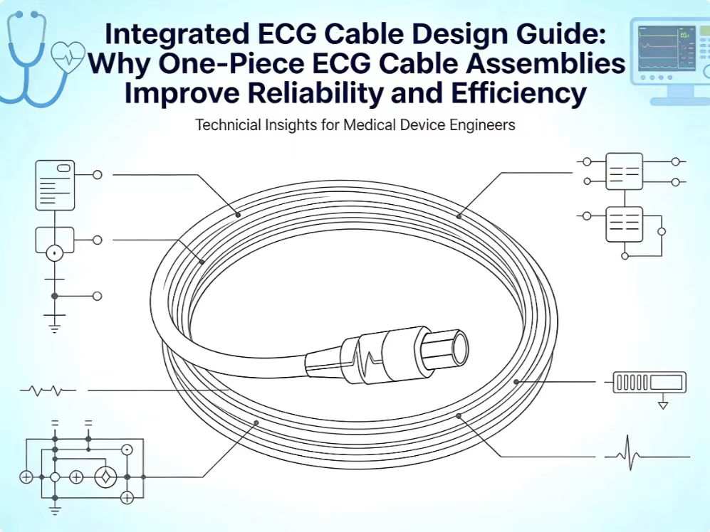
- Integrated ECG cable assemblies
- Reusable patient cables
- Application-specific patient monitoring systems
The exact construction depends on the device architecture and the requirements of the final application.
What Are ECG Leadwires?
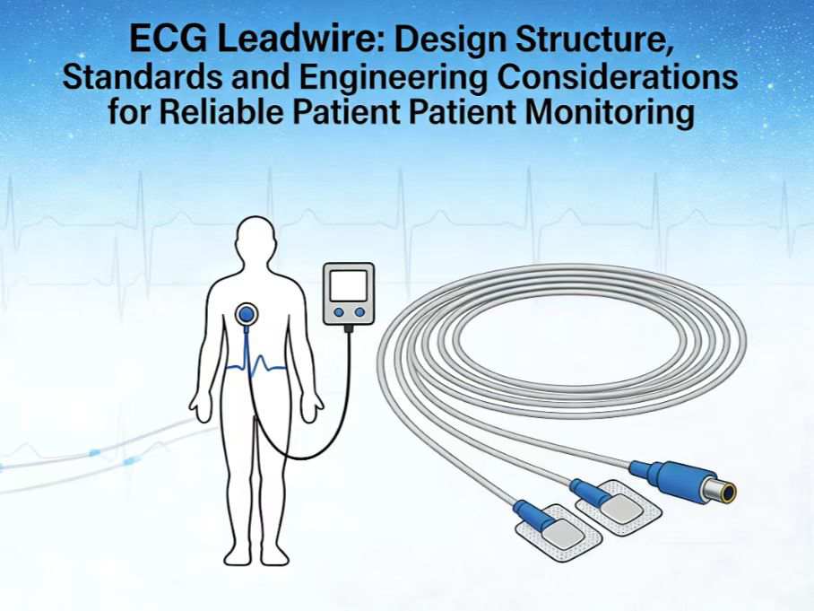
ECG leadwires are the patient-side conductors that connect electrodes to an ECG trunk cable or, in some device architectures, directly to a compatible monitoring device.
Leadwires can be configured in different lead counts, electrode termination styles, color-coding systems, cable lengths and mechanical constructions.
Common ECG leadwire configuration variables include:
- 3-lead, 5-lead, 10-electrode or custom configurations
- Snap, clip, grabber or other electrode terminations
- AHA, IEC or OEM-defined color coding
- Individual lead lengths
- Grouped or integrated leadwire construction
- Trunk-side connector type and pinout
- Jacket material and flexibility
- Shielding requirements
- Reusable or single-patient-use construction
- Cleaning and disinfection requirements
For a custom ECG leadwire project, the exact configuration should be established through an approved drawing, physical sample, connector information or interface specification.
A monitor brand or model name alone is generally not enough to determine the correct cable configuration or compatibility
How Do ECG Leadwires and Trunk Cables Work Together?
The ECG trunk cable and leadwire set form a connected patient monitoring system.
In a typical configuration:
Patient electrodes → ECG leadwires → patient-side connector/yoke → trunk cable → patient monitor
The leadwires provide the electrode connections and patient-side routing, while the trunk cable provides the main connection between the patient-side assembly and the monitoring device.
For example, a 5-lead patient monitoring cable may use individual leadwires with specific electrode terminations and color coding, while the trunk cable uses a device-specific connector and pinout to connect the assembly to the monitor.
The exact architecture can vary between devices. Some systems use detachable leadwire sets, while others integrate the leadwires and trunk cable into a single assembly.
Because both components affect the complete signal path and mechanical assembly, OEM teams should define the ECG cable system as a whole rather than selecting the trunk cable and leadwires independently.
A change in lead count, connector, electrode termination, pinout or color coding can affect the configuration of the entire assembly.
ECG Leadwire and Trunk Cable Compatibility: Why the Device Model Is Not Enough
One of the most common challenges in custom ECG cable development is determining compatibility from limited information.
A customer may provide a monitor brand and model and ask for a compatible ECG cable. However, the device name alone may not provide enough information to establish the complete cable configuration.
For an OEM or replacement cable project, the manufacturer may need to confirm:
- Monitor-side connector
- Connector dimensions and keying
- Pinout
- Lead configuration
- Electrode termination
- AHA or IEC color coding
- Cable length
- Cable outer diameter
- Shielding requirements
- Reusable or disposable construction
- Existing cable design or reference sample
Two cables may appear similar externally while having different connector pinouts or internal configurations.For this reason, compatibility should be verified against the actual interface requirements rather than determined from appearance or device model alone.
Key Design Considerations for ECG Cable OEM Projects
Before manufacturing begins, the ECG cable specification should address both electrical and mechanical requirements.
1. Device Interface
Which patient monitor, ECG module or diagnostic device will the cable connect to?
The monitor-side connector and interface should be clearly identified.
2. Lead Configuration
What lead configuration is required?
Common configurations include 3-lead and 5-lead systems, but custom configurations may also be required for specific applications.
3. Electrode Termination
Which patient-side electrode connector is required?
Depending on the application, this may include snap, clip, grabber or other project-specific termination styles.
4. Pinout
The connector pinout is an important part of cable compatibility. It should be confirmed from an approved drawing, specification or existing sample whenever possible.
5. Color Coding
Should the cable use AHA, IEC or customer-defined color coding?
Color coding should be defined together with the lead configuration and electrode assignment.
6. Cable Construction
The cable construction should be evaluated according to the intended application, including:
- Cable length
- Cable outer diameter
- Flexibility
- Jacket material
- Shielding
- Strain relief
- Mechanical durability
7. Reusable or Single-Patient-Use Design
A reusable ECG cable may require different material, mechanical and cleaning considerations compared with a single-patient-use assembly.
8. Packaging and Traceability
For medical device OEM projects, requirements may also include:
- Individual packaging
- Product labeling
- Lot identification
- Traceability
- Customer-specific packaging
- Inspection and testing requirements
Defining these requirements early can reduce compatibility risk and avoid unnecessary changes during sampling or mass production.
When Do You Need a Custom ECG Leadwire or Trunk Cable?
Standard ECG cables may be suitable when the required connector, lead configuration and electrode interface already match an established design.
However, customization may be necessary when the project requires a specific combination of:
- Monitor-side connector
- Pinout
- Lead count
- Electrode termination
- Color coding
- Cable length
- Cable diameter
- Jacket material
- Shielding
- Mechanical structure
- Packaging or labeling requirements
For medical device OEMs, customization does not necessarily mean designing every component from the beginning.
An existing cable or connector can often serve as a reference for developing a project-specific assembly, provided that the required interface and performance requirements can be clearly established.
The earlier these requirements are defined, the easier it is to evaluate feasibility, develop prototypes and move toward controlled production.
What Information Should You Provide When Requesting a Custom ECG Cable?
If you are developing or replacing an ECG cable for a patient monitoring system, providing detailed project information can significantly improve the engineering review and quotation process.
Ideally, provide as much of the following information as available:
| Information | Why It Matters |
| Device or monitor model | Helps identify the target application |
| Existing cable sample | Provides a physical reference for dimensions and construction |
| Connector photos | Helps identify the connector and interface |
| Technical drawing | Provides dimensional and interface information |
| Pinout | Defines electrical connections |
| Lead configuration | Determines the required number and arrangement of leads |
| Electrode termination | Defines the patient-side connection |
| AHA / IEC color coding | Determines lead identification |
| Cable length | Defines the overall assembly dimensions |
| Cable OD and flexibility | Helps determine cable construction |
| Reusable / disposable requirement | Affects materials and design |
| Annual or order quantity | Supports production and quotation planning |
| Packaging requirements | Defines final packing and labeling requirements |
If some information is not available, that does not necessarily mean the project cannot be evaluated.
Existing samples, connector photos, drawings and other available reference information can help the engineering team determine what additional information is required.If you are developing or replacing an ECG cable for a patient monitoring system, providing detailed project information can significantly improve the engineering review and quotation process.
Ideally, provide as much of the following information as available:
| Information | Why It Matters |
| Device or monitor model | Helps identify the target application |
| Existing cable sample | Provides a physical reference for dimensions and construction |
| Connector photos | Helps identify the connector and interface |
| Technical drawing | Provides dimensional and interface information |
| Pinout | Defines electrical connections |
| Lead configuration | Determines the required number and arrangement of leads |
| Electrode termination | Defines the patient-side connection |
| AHA / IEC color coding | Determines lead identification |
| Cable length | Defines the overall assembly dimensions |
| Cable OD and flexibility | Helps determine cable construction |
| Reusable / disposable requirement | Affects materials and design |
| Annual or order quantity | Supports production and quotation planning |
| Packaging requirements | Defines final packing and labeling requirements |
If some information is not available, that does not necessarily mean the project cannot be evaluated.
Existing samples, connector photos, drawings and other available reference information can help the engineering team determine what additional information is required.
From ECG Cable Requirements to Production
For OEM projects, selecting an ECG cable is not simply a matter of finding a connector that looks compatible.
The complete assembly needs to be considered from the device interface through to the patient electrode connection.
A typical development process may include:
Requirement Review → Engineering Evaluation → Prototype & Sampling → Validation → Controlled Mass Production
During the engineering review, the cable configuration, connector interface, lead arrangement, materials and mechanical requirements can be evaluated before production begins.
This approach helps reduce the risk of incompatibility and unnecessary redesigns later in the project.
Need a Custom ECG Leadwire or Patient Monitoring Cable?
If you are developing an ECG cable for a patient monitor, ECG module or other medical device, the required configuration may not match a standard catalog product.
JYCMED supports project-specific ECG leadwires and cable assemblies based on customer-defined requirements, including lead configuration, electrode termination, connector matching, color coding, cable construction and other application-specific requirements.
You can provide an existing cable, connector photos, drawings, pinout information or other available specifications for an initial engineering review.
[CTA: Discuss Your ECG Cable Project]
Conclusion
ECG leadwires and ECG trunk cables perform different functions, but they work together as part of the complete patient monitoring cable system.
The trunk cable primarily provides the interface between the monitoring device and the patient-side assembly, while the leadwires provide the connections between the cable system and patient electrodes.
For OEM projects, the correct ECG cable configuration should be defined based on the actual device interface, pinout, lead configuration, electrode termination, color coding, cable construction and application requirements—not simply the monitor brand or model.
By defining these requirements early, medical device OEMs can reduce compatibility risks, simplify prototype development and establish a clearer path from engineering review to validated production.