An ECG trunk cable may look similar to another cable at first glance, yet still be unsuitable for the intended patient monitoring system. The connector may fit physically, while the pin assignment, leadwire interface, shielding arrangement or identification requirements differ.
For that reason, a trunk cable should not be selected only by appearance, brand reference or the number of leads. Before ordering a replacement or starting a custom project, the monitor-side interface and electrical requirements need to be confirmed in a structured way.
What does “ECG trunk cable pinout” mean?
The pinout describes how the electrical contacts in a connector are assigned and connected inside the cable assembly. In an ECG trunk cable, that mapping may include signal channels, reference paths, shielding or grounding arrangements, identification circuits and other system-specific connections.
Two cables can use connectors that appear nearly identical but have different internal wiring. This is why a connector photograph alone is usually not enough to confirm compatibility.
A reliable review considers both sides of the assembly:
The monitor-side connector and its electrical contact arrangement
The leadwire-side interface
The required lead or electrode configuration
Cable length, branch structure and labeling
The electrical verification requirements for the finished cable
Start with the target monitor, not the cable photo
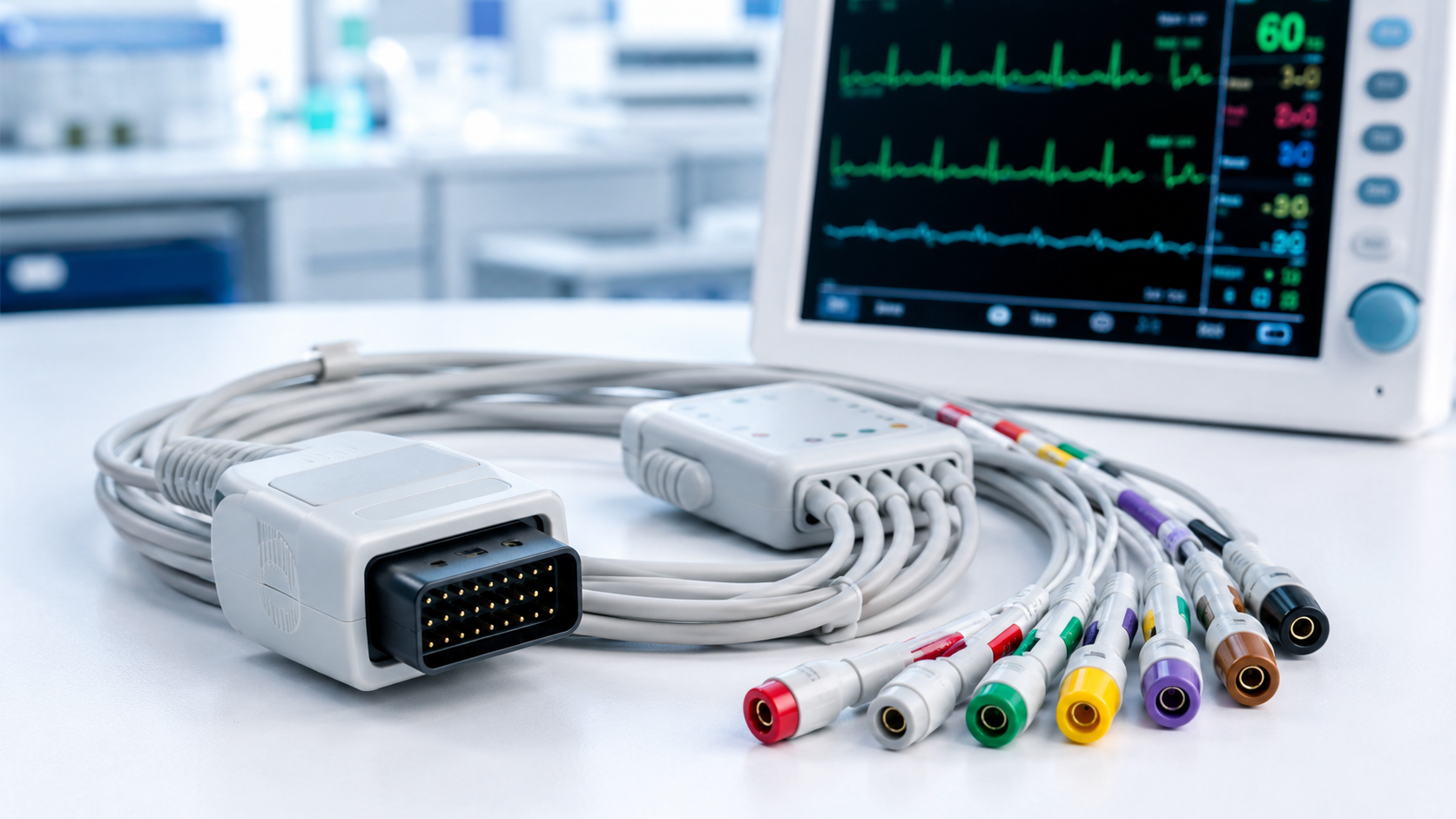
The most useful starting point is the exact equipment information. If available, provide the monitor manufacturer, model number and original cable part number. A clear photo of the original connector, including the front face and keying details, is also useful.
However, the original cable or a confirmed drawing remains more reliable than a photo alone. A sample allows the connector shape, contact layout, cable exit direction, locking features and overall construction to be reviewed together.
When an original part number is unavailable, the request should include as much project information as possible. This reduces the risk of assuming that a similar-looking cable uses the same electrical configuration.
Four details that should be confirmed before production
- Monitor-side connector and keying
The connector must match the target equipment mechanically. This includes the connector shape, pin count, gender, locking method, alignment features and cable exit orientation.
Mechanical fit is important, but it is only the first step. A correctly fitting connector does not automatically confirm that the cable is electrically compatible. - Electrical contact mapping
The contact mapping should be confirmed against an approved source such as a drawing, test record, original sample or verified project documentation.
This review may cover signal channels, reference connections, shielding, grounds and any system-specific electrical paths. The required mapping depends on the monitor and the lead configuration, so it should not be copied from a visually similar cable without verification. - Leadwire interface and configuration
The trunk cable must also match the intended patient-side leadwire set. The interface can vary by system, even where the monitor-side connector looks familiar.
Confirm the lead configuration required by the target system, such as 3-lead, 5-lead or a higher-electrode arrangement. Also confirm whether the system uses a particular color convention, branch layout or connector style for the patient leadwire connection. - Cable construction and identification
The electrical design is only one part of the specification. Cable length, branch length, jacket material, shielding approach, strain relief, labels and packaging requirements should be defined before the final build is approved.
These details matter because the cable may be used repeatedly in clinical environments where bending, handling, cleaning procedures and routine connection cycles affect the final construction requirements.
A practical information package for an ECG trunk cable inquiry
A concise request package helps avoid repeated clarification and makes the review more efficient. It should include:
Monitor manufacturer and model
Original cable part number, if known
Clear connector photographs or an original sample
Required lead or electrode configuration
Leadwire-side interface information
Required cable and branch lengths
Color coding, labeling or packaging requirements
Any available drawing, pinout table or electrical test requirement
If an approved drawing is not available, a sample can provide useful reference information. The final cable configuration should still be documented and confirmed before regular production begins.
For projects that need a monitor-side cable assembly built around an approved interface, review JYCMED’s ECG trunk cable options for patient monitoring systems.
Why “compatible with” needs careful review
Compatibility language can be misleading when it is based only on a brand or product family name. A single monitor manufacturer may use different connectors, pin assignments or leadwire interfaces across models and generations.
The safer approach is to identify the specific target device and confirm the cable requirements against the actual application. This protects both the buyer and the manufacturer from avoidable changes after samples have been reviewed.
Frequently asked questions
Is a matching connector enough to confirm ECG trunk cable compatibility?
No. The connector may fit mechanically while the internal pin assignment or leadwire-side interface differs. Both mechanical and electrical requirements should be checked.
Do I need to provide a wiring diagram?
A wiring diagram is helpful, but it is not always available. An original cable sample, confirmed part number and clear equipment information can also support the technical review.
Can one ECG trunk cable fit every monitor from the same brand?
Not necessarily. Connector style, pinout, cable construction and leadwire interface can differ between monitor models. Compatibility should be confirmed for the exact target system.
What should be tested before a cable is approved?
The required checks depend on the project. Typical verification may include continuity, pinout confirmation, insulation-related checks, visual inspection, labeling and workmanship review.
A well-defined trunk cable specification begins with the actual monitor interface and ends with an approved cable configuration. Taking the time to verify the pinout before ordering is usually far simpler than correcting an incompatible assembly later.