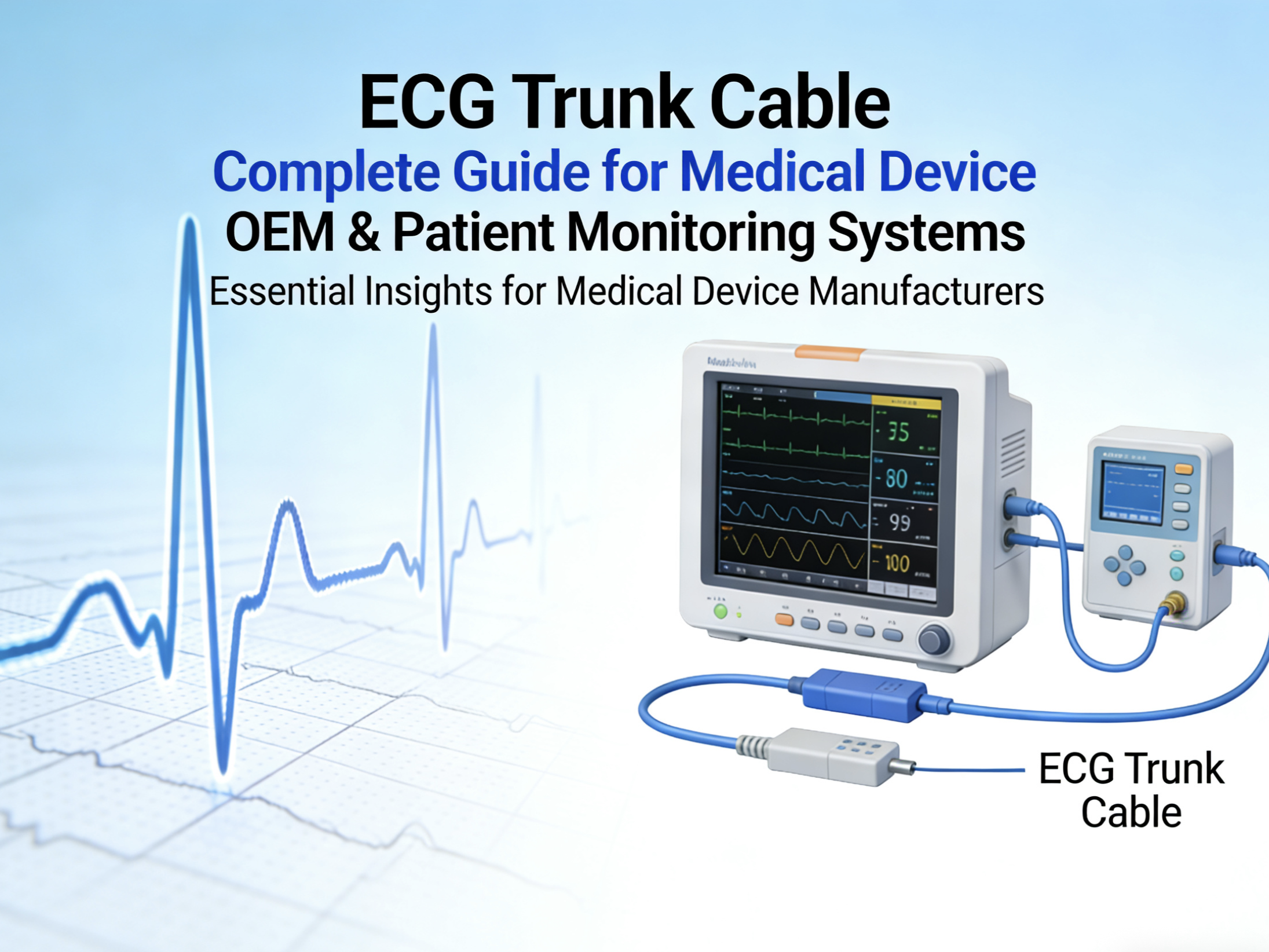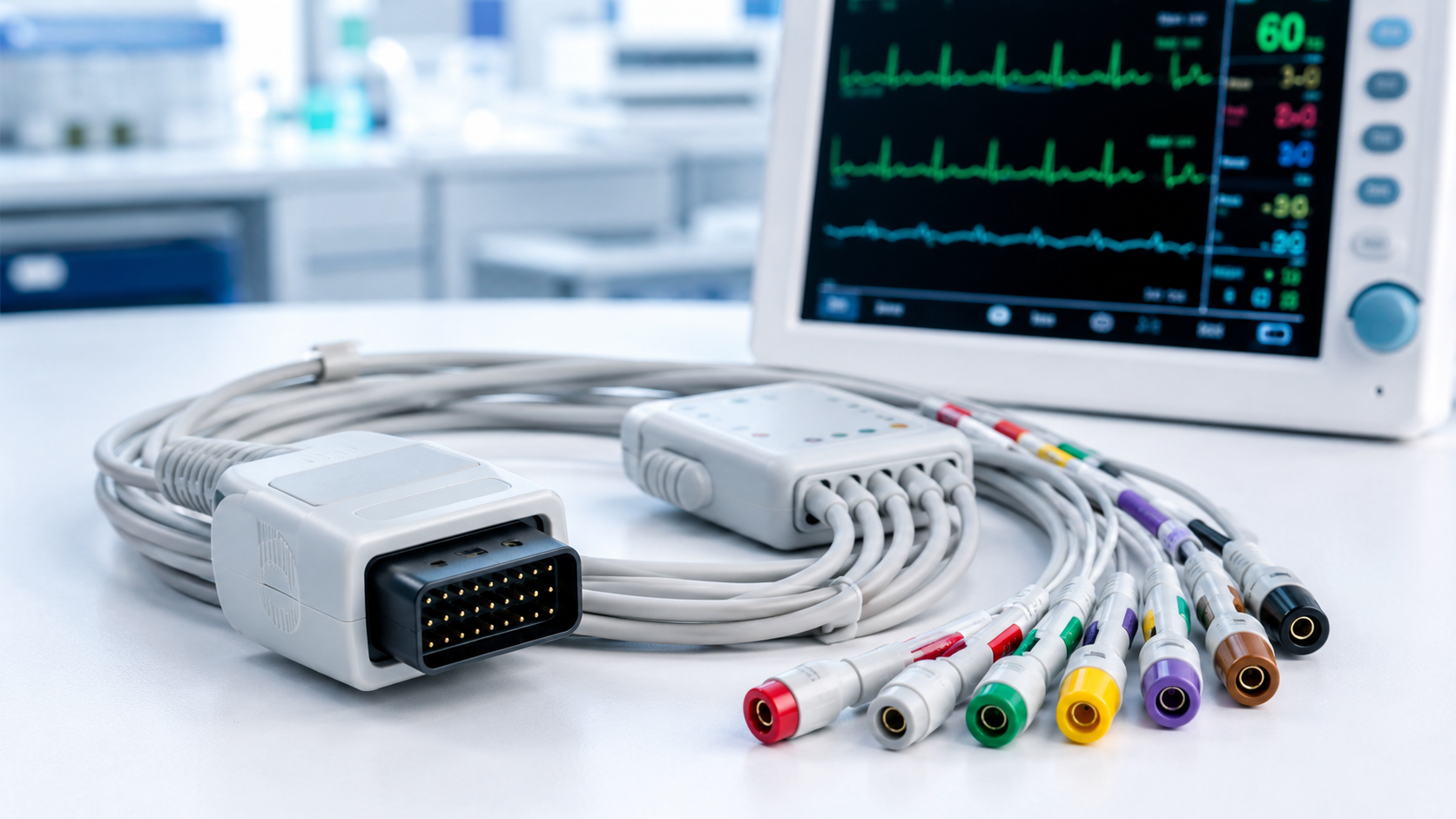
When buyers request an ECG trunk cable, the lead configuration is often one of the first details mentioned. A request may refer to a 3-lead cable, 5-lead cable or 10-electrode cable. That information is important, but it does not define the complete cable assembly by itself.
The target monitor, connector layout, pinout, leadwire interface and intended use all influence the final specification. A clear configuration review helps ensure that the finished cable is suitable for the actual monitoring system rather than simply similar to an existing cable.
Lead configuration is not the same as connector compatibility
A 3-lead, 5-lead or 10-electrode description usually refers to the patient monitoring arrangement required by a particular system. It does not automatically identify the monitor-side connector, electrical contact mapping or leadwire connection method.
For example, two 5-lead ECG systems may use different monitor connectors or different leadwire interfaces. The cable length, branch structure, color convention and labeling requirements may also differ.
This is why an ECG trunk cable should be specified as a complete assembly, not only by the number of leads.
Understanding common ECG cable configurations
3-lead ECG configurations
A 3-lead configuration is commonly used where a simpler patient monitoring arrangement is required. The exact cable design still depends on the target monitor and leadwire set.
Before ordering, confirm the monitor model, connector style, leadwire interface, branch structure and any required color coding. Do not assume that all 3-lead cables are interchangeable.
5-lead ECG configurations
A 5-lead configuration supports a different monitoring arrangement and may require additional conductors, branches or specific electrical mapping compared with a 3-lead version.
The correct cable depends on how the target system defines and processes its ECG channels. A buyer should confirm the required monitor-side pinout and patient leadwire connection before the cable layout is finalized.
10-electrode ECG configurations
Some monitoring or diagnostic systems use a 10-electrode patient connection arrangement. Depending on the target system, those electrode inputs may support a broader ECG display or recording configuration.
Terminology can vary between equipment manufacturers. A request for a “10-lead cable” may not describe the same requirement as a request for a “10-electrode cable.” The safest approach is to use the equipment documentation, original cable part number or an approved sample as the reference.
Details that change when the configuration changes
A different lead configuration can affect more than the number of conductors inside the cable. It may also change:
The monitor-side connector and pin assignment
The leadwire-side interface
The cable branch layout
The required cable and branch lengths
Color coding or lead identification
Shielding requirements
Strain-relief construction
Labeling, packaging and traceability requirements
For this reason, a cable intended for one configuration should not be assumed to work with another configuration unless the target system documentation confirms it.
Avoid confusing lead count with conductor count
“Lead count” is often used in purchasing conversations, but it should not be treated as a complete electrical description. The number of conductors inside the cable may be influenced by shielding, reference paths, identification features and the specific system design.
Instead of relying on a short description such as “5-lead ECG cable,” it is better to confirm the complete requirement:
Which monitor model will the cable connect to?
What is the required monitor-side connector?
What is the approved pinout?
Which leadwire set will be used?
What cable and branch lengths are required?
Which color standard or labeling convention applies?
Is there an existing sample or drawing for reference?
These questions help turn a broad product request into a practical manufacturing specification.
Using samples and drawings effectively
An original sample is useful because it can show the physical connector, cable exit direction, branch layout, labels and general construction. A sample alone may not reveal every electrical requirement, so it should be reviewed together with available equipment information and documentation.
Where a drawing is available, it should identify the connector, pin assignment, cable length, branch lengths and labeling details. Once the configuration has been agreed, the final cable construction can be documented for sample verification and controlled production.
When the configuration is ready for review, see JYCMED’s ECG trunk cable assemblies for patient monitoring systems for the key project details that can be defined.
Frequently asked questions
Can a 3-lead trunk cable be used with a 5-lead system?
Not by assumption. The monitor connector, electrical mapping and leadwire interface must match the target system. The device documentation should be checked first.
Does a 10-electrode cable always mean a 12-lead ECG cable?
Not necessarily. Some systems use 10 electrode inputs to derive a broader ECG display, but the capability depends on the monitor and its intended configuration.
Is the original cable part number useful?
Yes. An original part number can help identify the target configuration, especially when paired with monitor model information, photographs or a physical sample.
What is the best way to request a custom configuration?
Provide the monitor model, original cable reference if available, required lead configuration, connector information, cable lengths and any drawing or sample. This gives the supplier a clear basis for reviewing the assembly.
The best ECG trunk cable specification is specific enough to remove guesswork. Confirming the configuration at the beginning helps the finished cable match the monitor, leadwire set and intended workflow more reliably.